
|
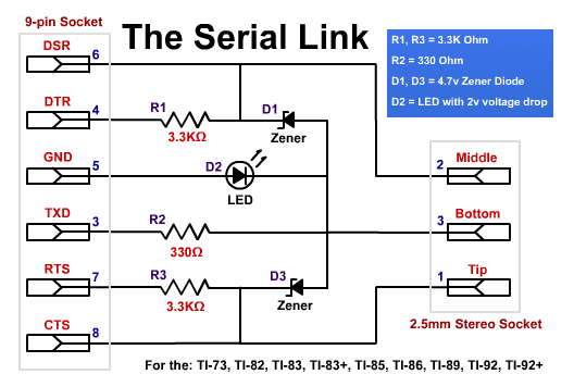
Serial Link Schematics

|
About the Serial Link
This linking cable is used to connect your Texas Instruments Graphing calculator to your computer via the serial port to give you the ability to load programs (and more) from your computer to the calculator and vice versa.
One can use TI-Graph Link™ and TI Connect™ software with this cable since it is 100% compatible with the Black Cable from Texas Instruments. Also this cable is faster in loading items onto the calculator compared to the Black Cable, since it doesn't use transistors.
| Compatibility of this cable including third party software |
| Platform |
Calculator Models |
| Win 32-bit: |
TI-73, TI-82, TI-83, TI-83+, TI-85, TI-86, TI-89, TI-92, TI-92+ |
| Win 16-bit: |
TI-73, TI-82, TI-83, TI-83+, TI-85, TI-86, TI-89, TI-92, TI-92+ |
| Linux: |
TI-82, TI-83, TI-83+, TI-85, TI-86, TI-89, TI-92, TI-92+ |
| Mac OS: |
None |
| Amiga: |
TI-85, TI-92 |
| Atari: |
TI-82, TI-83, TI-83+, TI-85, TI-86, TI-89, TI-92 |
| DOS: |
TI-82, TI-83, TI-83+, TI-85, TI-86 |
|
|
Building the Serial Link
Here in this document are instructions on constructing your own Serial Link. If you have no idea about what the schematics below are about, then you may encounter some difficulties trying to building this link. If you would like to build a simpler Link, the Parallel Link is one but it is unreliable and and not compatible with the TI-Graph Link™ and TI Connect™ software.
| The Schematics |
 |
| Materials Needed |
Equipment Needed |
|
|
- Soldering Iron
- Wet Sponge
- Solder
- Clamps and/or a Vice to assist you
- Wire Stripers and Pliers.
- Multimeter
- Phillips Head Screw Driver
- Drill
|
Set up and Safety
When soldering make sure you are in a well ventilated area due to the fumes created by the heated flux in the solder. Once you have finished soldering make sure you wash your hands because the solder contains a small amount of lead, which is poisonous and can penetrate your skin if you don't remove it. If you are worried about this fact you may use gloves but they hinder the mobility of your hands. To be extra safe, wear glasses for eye protection and an apron so you don't burn your clothes by accident.
When setting up your work area have everything neatly in their places so you can easily access everything. The sponge is used to clean the tip of the soldering iron when it becomes dirty.
| Detailed Instructions |
- Turn on the soldering iron to heat it up.
- Prepare the parts: bend the wires on the LED 90° and trim the wires so that about 5mm remains on both sides. Trim one of the wires on each resistor so that about 5mm of that wire remains. Trim the wire on the side with the line (cathode) so that about 5mm remains, on each diode.
- Use the soldering iron to pre-solder the points 3, 4, 5, 6, 7 and 8 on the DB-9 socket. (The numbers are displayed next to the pins, and don't solder on the holes you plug into the computer).
- Heat up the solder in pin 5 on the DB-9 connector and stick in the LED's wire with the flat side of the LED facing up (the 'a' side in and the 'k' side up). Solder the 5mm long wire of the resistors into; 330 Ohm into pin 3 and the two 3.3K Ohm into pins 4 & 7 (separately). Solder the Zener diodes with the lined side ('k') into the pins 6 & 8 (separately).
- Bend the top wire of the diode on pin 9 to touch the top wire on the LED and solder them together.
- Bend the top wire of the resistor on pin 3 to touch the top wire of the diode on pin 9 and solder them together.
- Bend the top wire of the diode on pin 6 to touch the top wire of the resistor on pin 3 and solder those together.
- Bend the top wire of the resistor on pin 7 to touch the bottom wire of the diode on pin 8 and solder those together.
- Bend the top wire of the resistor on pin 4 to touch the bottom wire of the diode on pin 6 and solder those together (make sure the wire doesn't touch anything else, this applies to all wires).
- Strip (carefully!) about 1cm off the cable (both ends), and strip a further 5mm off the inside wires (both ends) and cut off any left over wires if you are using a 4 or more core cables, cut them off on both ends and make sure you only cut off the same wires at each end).
- Separately, twist the exposed copper strands from each wire and pre-solder them.
- Open up the 2.5mm Stereo socket, you will see three contacts (two little ones (one copper coloured) and one big one). Connect one wire (or the shielding) to the big connector via threading the copper wire through the hole and soldering it on, and cut off the rest that sticks out. Solder, preferably the red coloured cable to the copper connector and the white one to the other silver connector. We assume the copper connector is the Tip, the silver one is the Middle and the big connector is the Bottom, you may want to use a multimeter to verify that this is true for your 2.5mm socket.
- Slide on the cover for the 2.5mm socket over the cable and screw it back onto the socket after you have verified that the Serial Link works.
- Assuming the information is correct in step 12; connect the red coloured wire to the wire on the top of the resistor on pin 8 (on the DB-9 socket), the white wire to the top of the resistor on pin 4 and the other wire on the section of wire that connects to the top of the diodes.
- The electronics part of the cable is now finished, you must check that there are no short circuits, and that all connections have been properly soldered. You may test this with the multimeter on both the DB-9 and the 2.5mm socket.
- Once you have verified that you have properly soldered and connected all the components, plug the cable into the computer, if the LED lights up, then that's a good sign, if it doesn't it either means that your computer is turned off, the serial port isn't initiated (could be if your not using Windows) or something is wrong with your link. If it does light up, connect your calculator and launch the version of TI-Graph Link™ for your calculator, set it to connect on the correct serial port, set the cable type to Black Cable. Now turn on your calculator and either take a screen shot of the calculator or load a program to it, and if that works, it works. If it doesn't make sure you have correctly constructed the cable, that the TI-TI cable has a proper connection through the 2.5mm socket (test using a multimeter), and make sure you have used the correct parts.
- Drill a 6.35mm hole in the top of the cover where the LED will poke through (make sure you drill it in the right spot). Insert the bezel in to the hole; now attach the cover on to the 9-pin socket (and over the components).
- Congratulations you have finished your Serial Link.
|
Additional Information
Check out our Features article to find out what types of programs are available for your TI and where to download them.
For another set of instructions to make this cable visit ticalc.org.
If you can't make your own cable buy an official cable from Texas Instruments.
The original schematics of this Serial Link has been designed by Timo Stenberg.
|
| The displayed information is provided on an 'as is' bases, Pacmeb and any one associated with Pacmeb or this information is not responsible for the usage of this information and there for isn't liable for any damage resulting from it. The authors of the software listed and the creators of this device aren't responsible for any damage this information may cause. |
|
|